This topic explains how to configure the layout of the xamDiagram™ and how to create a custom layout scheme.
The following topics are prerequisites to understanding this topic:
This topic contains the following sections:
There are two ways to position nodes in the xamDiagram – by setting the DiagramNode.Position property or the XamDiagram.Layout property. Currently three predefined layouts are available – ForceDirectedGraphDiagramLayout, TreeDiagramLayout and GridDiagramLayout. Custom layouts are supported through implementations of the IDiagramLayout interface. The IDiagramLayout interface has a single ArrangeNodes method that accepts a single IEnumerable<DiagramNode> parameter. In this method the Position property of the provided nodes must be set according to the desired layout scheme.
The following table briefly explains the configurable aspects of the xamDiagram layout and maps them to the API that configure them.
To set the layout of the xamDiagram , set its Layout property to an instance of the provided ForceDirectedGraphDiagramLayout, TreeDiagramLayout or GridDiagramLayout classes or a custom IDiagramLayout implementation.
The following table maps the desired configuration to the property settings that manage it.
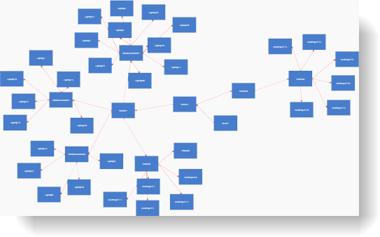
The screenshot below demonstrates how a xamDiagram looks with its Layout property set to a ForceDirectedGraphDiagramLayout instance:

Following is the code for applying the ForceDirectedGraphDiagramLayout.
In XAML:
<ig:XamDiagram>
    <ig:XamDiagram.Layout>
        <ig:ForceDirectedGraphDiagramLayout />
    </ig:XamDiagram.Layout>
    …
</ig:XamDiagram>The following procedure explains how to create a custom layout that will position the diagram nodes sequentially in a down-right direction.
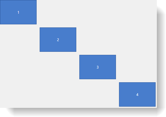
The following screenshot is a preview of the result.

To complete the procedure, you need the following:
A WPF application with the assemblies required by the xamDiagram as listed in Adding xamDiagram to a Page.
The following steps demonstrate how to create a custom diagonal layout.
Create a class implementing the IDiagramLayout interface.
Create a new DiagonalLayout class that implements the IDiagramLayout interface. In the ArrangeNodes method iterate over the nodes and set the Position of each node to the bottom-right corner of the Bounds rectangle of the previous node. In this example an additional Offset property is added to control the spacing between nodes. Refer to the Full code for the implementation details.
In order to apply the diagonal layout set an instance of the DiagonalLayout class.
Following is the full code for this procedure.
In C#:
namespace XamDiagramSample
{
    public class DiagonalLayout : IDiagramLayout
    {
        public double Offset { get; set; }
        public void ArrangeNodes(IEnumerable<DiagramNode> nodes)
        {
            Point nextPoint = new Point(0,0);
            foreach (DiagramNode node in nodes)
            {
                node.Position = nextPoint;
                nextPoint = new Point(node.Bounds.Right + Offset, node.Bounds.Bottom + Offset);
            }
        }
    }
}
In Visual Basic:
Namespace XamDiagramSample
    Public Class DiagonalLayout
        Implements IDiagramLayout
        Public Property Offset As Double
        Public Sub ArrangeNodes(nodes As IEnumerable(Of DiagramNode)) Implements IDiagramLayout.ArrangeNodes
            Dim nextPoint As New Point(0, 0)
            For Each node As DiagramNode In nodes
                node.Position = nextPoint
                nextPoint = New Point(node.Bounds.Right + Offset, node.Bounds.Bottom + Offset)
            Next
        End Sub
    End Class
End Namespace
In XAML:
<ig:XamDiagram x:Name="Diagram"
        xmlns:local="clr-namespace:XamDiagramSample">
    <ig:XamDiagram.Layout>
        <local:DiagonalLayout Offset="10"/>
    </ig:XamDiagram.Layout>
    <ig:DiagramNode Content="1"/>
    <ig:DiagramNode Content="2"/>
    <ig:DiagramNode Content="3"/>
    <ig:DiagramNode Content="4"/>
</ig:XamDiagram>The following topic provides additional information related to this topic.